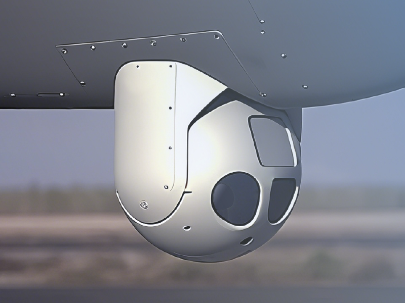
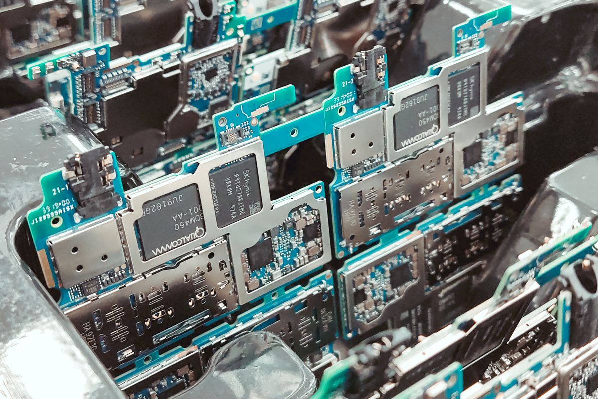
Selecting thermal camera cores for an OEM product is rarely a single-parameter decision. Resolution, waveband, NETD, lens compatibility, frame rate, video interface, image processing, size, power, export classification, and lifecycle support all affect whether the module will work reliably in the final system. Many selection errors occur because engineers compare datasheet values in isolation instead of matching the infrared core to target physics, operating environment, mechanical envelope, software pipeline, and production constraints.
How Do Thermal Camera Cores Work in OEM Systems?
A thermal camera core is the imaging subsystem that converts infrared radiation into digital image data for a host product. It typically includes the detector, readout electronics, signal processing, timing control, calibration data, and one or more video or data interfaces. Unlike a finished thermal camera, a core is intended to be embedded into another product such as a gimbal, vehicle perception unit, inspection instrument, security payload, or industrial monitoring device.
A common mistake is treating the core as if it were only a sensor. The detector is important, but OEM performance depends on the whole imaging chain. A high-quality detector can still deliver poor field performance if the optics are mismatched, calibration is unstable, integration latency is excessive, or the host processor cannot handle the data stream. Conversely, a lower-resolution core with appropriate optics and stable calibration may outperform a higher-resolution module in a constrained embedded system.
Another frequent error is assuming that all infrared images measure temperature in the same way. Many OEM thermal cores are optimized for imaging contrast, detection, or navigation rather than calibrated radiometry. For condition monitoring and power inspection, radiometric accuracy, emissivity handling, reflected temperature assumptions, and calibration traceability matter. For surveillance and vehicle perception, contrast, latency, dynamic range, and scene adaptation may be more important than absolute temperature output.
OEM teams should define the imaging task before selecting the module: detect, recognize, identify, measure, classify, track, or guide. A border security payload, for example, may prioritize long-range target detection and stabilized video, while a mobile robot may need low latency, compact size, and a host-friendly interface. The same nominal resolution can lead to different product outcomes depending on the mission profile.
Thermal Camera Cores vs Complete Thermal Cameras: What Should OEMs Compare?
Complete thermal cameras are usually designed as end products with enclosure, lens, control software, environmental sealing, and user-facing features already defined. Thermal camera cores are integration components. The OEM must provide the mechanical housing, optical path, thermal design, power supply, user interface, data recording, and system-level validation. Confusing these categories can lead to underestimating engineering effort.
One mistake is comparing a finished camera’s published performance directly with a bare module’s datasheet. A finished camera may include application-specific sharpening, contrast enhancement, image stabilization, network streaming, radiometric tools, or environmental compensation. A core may expose rawer image data and require the OEM to tune non-uniformity correction, automatic gain control behavior, or video encoding in the host system.
Interface assumptions are another source of integration risk. MIPI CSI-2, LVDS, Camera Link, USB, Ethernet, SDI, and analog outputs each carry different implications for cable length, electromagnetic compatibility, latency, bandwidth, software driver effort, and connector design. ONVIF’s Profile T is relevant when IP video interoperability is required, but many embedded cores are not network cameras by themselves. If an OEM system requires ONVIF-compatible streaming, that requirement may belong to the processing board or imaging system layer, not the detector module alone.
Thermal design is often underestimated. Uncooled LWIR cores need stable operating conditions for repeatable image quality, while cooled MWIR cores add compressor power, cool-down time, vibration, service-life considerations, and mechanical accommodation. The mistake is not choosing cooled or uncooled technology; the mistake is choosing it without accounting for the total product architecture.
For compact embedded products, modules such as SPECTRA L06 640×512 LWIR 12μm are typically evaluated for size, power, and integration efficiency. Larger-format systems such as SPECTRA L12 1280×1024 LWIR may be appropriate where wider coverage or more pixels on target justify the bandwidth, optics, and processing cost.
When to Use LWIR, MWIR, SWIR, or Dual-Band Thermal Camera Cores
A major selection error is starting with resolution before selecting the waveband. The infrared band determines which physical phenomena the camera can see. LWIR, MWIR, and SWIR are not interchangeable labels; they respond differently to temperature, atmosphere, reflected light, glass transmission, solar background, smoke, humidity, target materials, and optics.
LWIR cores are commonly used for uncooled thermal imaging because many terrestrial-temperature objects emit strongly in the 8-14 μm region. They are suitable for many security, industrial, robotics, and vehicle applications where compactness, lower power, and no cryocooler are important. However, LWIR optics are not ordinary visible-light glass, and image behavior can change with window material, lens F-number, and environmental temperature.
MWIR cores are often selected for longer-range imaging, hot targets, high-speed thermal events, and applications where cooled detector sensitivity and optical performance justify the added complexity. The mistake is assuming cooled MWIR is always better. It can deliver strong performance, but the OEM must budget for cool-down time, cryocooler lifetime, power draw, acoustic or mechanical effects, and maintenance expectations. A module such as SPECTRA M06 640×512 Cooled MWIR 15μm is usually evaluated in systems where detection range, sensitivity, and optical design outweigh the added integration burden.
SWIR is different again. It often images reflected light in the 0.9-1.7 μm region rather than emitted thermal radiation from ambient-temperature objects. SWIR can be useful for seeing through some obscurants, imaging laser spots, inspecting materials, or working with low-light scenes, but it should not be selected as a direct substitute for LWIR thermal imaging. For applications that need this band, SPECTRA S06 640×512 SWIR 0.4–1.7μm belongs in a different trade study than an LWIR thermal core.
Dual-band modules can reduce ambiguity by combining complementary information, such as thermal contrast and visible detail. They are often useful when operators or algorithms need both heat signatures and scene context. The integration mistake is treating dual-band as a simple resolution upgrade. Registration accuracy, time synchronization, field-of-view matching, processing latency, and calibration workflow become central. For systems needing fused visible and LWIR data, FUSION LV0625A 640×512+2560×1440 MIPI 35mm is an example of the type of architecture that should be evaluated as a combined imaging subsystem rather than as two independent cameras.
What Specifications Matter Most When Choosing Thermal Camera Cores?
NETD is one of the most misunderstood specifications. A low NETD value indicates the ability to distinguish small temperature differences under defined test conditions, but it does not automatically guarantee better detection in the field. Lens F-number, integration time, image processing, scene temperature, calibration state, and atmospheric path all influence usable contrast. OEM buyers should ask how NETD was measured and whether the conditions match the intended optical configuration.
Resolution is also frequently overvalued. More pixels can improve coverage or pixels-on-target, but only if the optics provide adequate modulation transfer, the platform can stabilize the line of sight, and the system can process the data. ISO 12233:2024 covers methods for measuring digital camera resolution and spatial frequency response at the camera level, and it is a useful reminder that image sharpness is a system property, not just a pixel count. The standard is listed by ISO at ISO 12233:2024.
Pixel pitch affects optical design, module size, sensitivity, and sampling. A smaller pixel pitch can support compact optics and higher pixel density, but it may require careful lens selection and may not always improve range if sensitivity, diffraction, or aperture constraints dominate. A larger pixel pitch may be beneficial in cooled systems where sensitivity and long-range optics are central.
Frame rate and latency should be evaluated together. A camera core may output a nominal 50 Hz or 60 Hz video stream, but system latency includes exposure, readout, processing, interface transport, host decoding, display, and algorithm execution. For vehicle, UAV, tracking, and fire-control-adjacent applications, latency variance can matter as much as average latency.
Image processing features require close review. Non-uniformity correction, bad-pixel replacement, automatic gain control, local contrast enhancement, digital zoom, polarity modes, and radiometric output can be valuable, but they also affect algorithm input consistency. A core tuned for human viewing may not provide the most stable input for machine perception. When AI inference is part of the system, modules or systems such as NEXUS LV0619B AI multi-band Ethernet/SDI should be evaluated at the pipeline level: sensor data, synchronization, processing hardware, model deployment, video output, and maintainability.
Specification comparability is a final concern. The EMVA 1288 standard was created to improve objective characterization and presentation of camera and sensor parameters for machine vision. Its overview at EMVA 1288 is useful background when comparing sensitivity, noise, and camera characterization claims, even though infrared OEM modules may also require band-specific and application-specific tests beyond general machine-vision metrics.
The practical conclusion for OEM selection is straightforward: do not choose a thermal core from a single headline number. Build the selection around target signature, range, field of view, waveband, optics, interface, power, thermal control, calibration, software pipeline, compliance, and production lifetime. A good module choice is the one that fits the complete product architecture with enough margin for manufacturing and field conditions.
FAQ: Common Questions About Choosing Thermal Camera Cores
What is the biggest mistake when choosing a thermal camera core?
The biggest mistake is selecting by resolution alone. Resolution matters, but it must be evaluated with waveband, optics, sensitivity, field of view, target size, atmospheric path, latency, power, and processing requirements. A higher-resolution core can underperform if the lens, interface, or host processor cannot support the intended use case.
How do I choose between LWIR and MWIR thermal camera cores?
Choose LWIR when compact size, lower power, uncooled operation, and general thermal imaging of ambient-temperature scenes are priorities. Choose MWIR when the application requires cooled sensitivity, long-range performance, hot-target imaging, or specific atmospheric and optical advantages. The correct choice depends on target temperature, range, aperture, environmental conditions, and lifecycle constraints.
Is lower NETD always better for OEM thermal imaging?
No. Lower NETD can indicate better temperature-difference sensitivity under defined conditions, but field performance also depends on optics, F-number, calibration, image processing, atmospheric transmission, and scene dynamics. OEMs should compare NETD only when measurement conditions and optical assumptions are clear.
When should an OEM use a dual-band thermal module?
Use a dual-band module when one band cannot provide enough information for the task. Examples include thermal detection with visible identification, operator situational awareness, machine perception, and applications where fused context reduces false alarms. The OEM should validate alignment, synchronization, latency, and calibration stability before committing to production.
What should be included in a thermal camera core selection checklist?
A practical checklist should include waveband, detector type, resolution, pixel pitch, NETD, frame rate, latency, field of view, lens options, video interface, command protocol, power, size, weight, operating temperature, calibration method, radiometric requirements, image processing controls, export status, supply continuity, and application-level validation results.