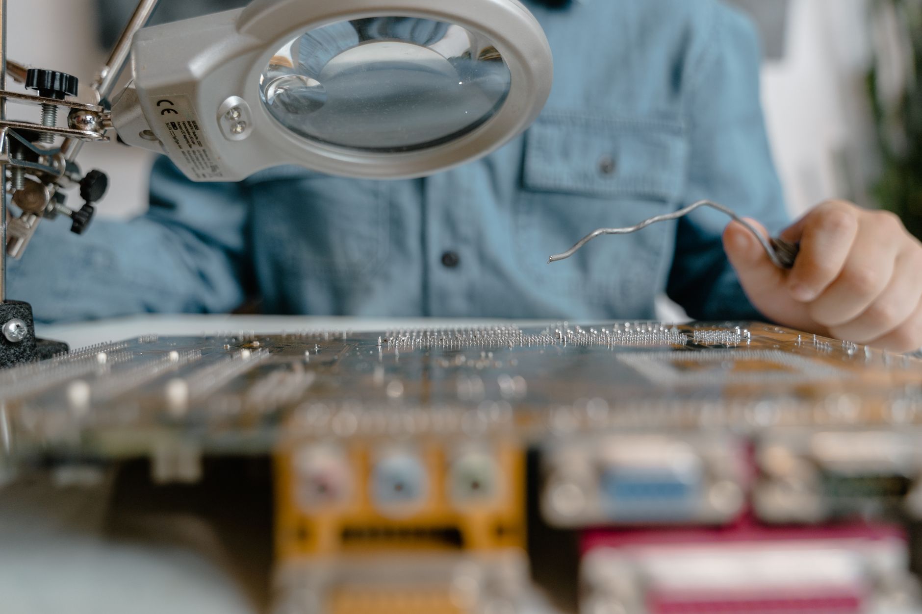
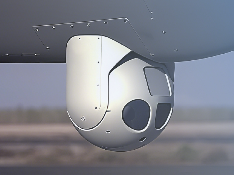
Sample testing for thermal camera modules should verify more than whether an image appears on a display. For OEM engineers, the sample stage is the point where detector format, lens behavior, radiometric stability, interface timing, mechanical fit, firmware control, and production repeatability are tested against the intended system architecture. A useful checklist turns the evaluation from a subjective image review into a controlled comparison of performance, integration risk, and lifecycle suitability.
How Do Thermal Camera Modules Work in Sample Testing?
A thermal camera module converts infrared radiation into an electrical signal, processes that signal into image data, and outputs a video or digital stream for integration into a host system. In sample testing, the engineer is not only checking detector sensitivity. The test should confirm the complete imaging chain: optics, focal plane array, non-uniformity correction, image signal processing, timing, control protocol, power behavior, thermal management, and environmental response.
The first step is to define the target use case before powering the sample. A module for perimeter observation, vehicle perception, UAV payloads, or electrical inspection will have different acceptance criteria. A long-range observation system may prioritize narrow-field optics, low noise, image stability after zoom or focus changes, and support for continuous operation. A compact robotic platform may prioritize board-level size, power consumption, latency, digital interface compatibility, and behavior during rapid temperature changes.
The sample should be tested in the same output mode expected in the final product. If the OEM system will ingest RAW data, the evaluation must include RAW frame integrity, bit depth, synchronization, and calibration metadata. If the product will use processed video, then tone mapping, automatic gain control, overlay behavior, and compression artifacts become part of the acceptance test. For network-connected products, interoperability should be checked against the relevant client software and transport requirements; for example, ONVIF Profile T is often referenced when video streaming, encoding, imaging settings, and metadata behavior must be aligned with security video systems.
Thermal Camera Modules Testing Checklist: What Parameters Matter?
A practical sample checklist should start with identity and configuration control. Record the module model, detector resolution, pixel pitch, spectral band, lens part number, firmware version, calibration file version, output interface, frame rate, and enabled image-processing functions. Without this baseline, two samples that appear identical can produce different results because of firmware, lens, or calibration differences.
Image quality testing should cover noise, uniformity, bad-pixel correction, contrast rendition, edge response, focus stability, and image artifacts. NETD is an important reference parameter, but it should not be treated as the entire image-quality result. Engineers should observe temporal noise in a stable scene, fixed-pattern noise after warm-up, behavior after non-uniformity correction, and visible artifacts near high-contrast edges. For machine-vision-style characterization, the EMVA 1288 framework is a useful reference because it defines objective measurement and presentation methods for camera and sensor performance, even when additional infrared-specific tests are required.
Radiometric testing is required when the module will support temperature measurement rather than observation only. Use calibrated blackbody sources or traceable reference targets across the expected temperature range. Record accuracy, repeatability, drift after warm-up, spatial variation across the field, and sensitivity to emissivity assumptions. The test should separate camera signal stability from scene uncertainty; surface emissivity, reflected apparent temperature, distance, atmosphere, and lens transmission can dominate the final measurement error. NIST has published work on calibration and measurement procedures for thermal cameras, which is relevant when uncertainty must be treated explicitly rather than estimated informally.
Interface testing should confirm electrical compatibility and timing under real host conditions. MIPI, Camera Link, LVDS, USB, GigE, SDI, and Ethernet outputs have different risks. The sample test should measure frame delivery, dropped frames, boot time, command response, trigger behavior, synchronization accuracy, and recovery after cable disconnect or power interruption. If the host system uses embedded processing, test CPU, memory, and bandwidth load with the actual image format and frame rate.
Mechanical and optical checks should include lens alignment, focus range, back focal distance sensitivity, aperture behavior, sealing concept, connector retention, board mounting, shock path, and service access. A module that produces acceptable laboratory images may still be unsuitable if its lens cannot be locked, its connector conflicts with the enclosure, or its heat path changes focus during operation. For uncooled LWIR integration, a module such as SPECTRA L06 640x512 LWIR 12um should be evaluated with the intended lens, enclosure window, and processor board rather than as an isolated imager.
Power and thermal behavior should be measured throughout startup, stabilization, steady operation, and mode switching. Record inrush current, average power, peak power, housing temperature, image drift with internal temperature, and recovery after rapid ambient changes. For battery-powered platforms, power variation during calibration events or shutter operation can be as important as average consumption.
Cooled vs Uncooled Thermal Camera Modules: Which Sample Tests Change?
Uncooled LWIR modules and cooled MWIR modules require different sample-test priorities. Uncooled modules usually offer lower size, weight, power, and cost, but their images can be more sensitive to internal temperature changes, lens transmission variation, and non-uniformity correction behavior. Testing should emphasize warm-up time, shutter or shutterless correction strategy, stability over ambient temperature, and performance after repeated power cycles.
Cooled MWIR modules introduce additional checks because the cryocooler is part of the imaging chain. The sample test should record cool-down time, cooler power, acoustic and vibration behavior, image quality at operating temperature, cooler duty cycle, and expected lifetime assumptions. Cooled modules can provide strong sensitivity and long-range performance, but the OEM must verify that the cooler’s power, thermal load, startup time, and maintenance profile match the platform.
Spectral band also changes the scene content being tested. LWIR is commonly used for passive thermal contrast in many terrestrial scenes. MWIR can be advantageous for long-range imaging, high-temperature targets, and certain atmospheric windows, but it depends on cooling and optics suited to the band. A cooled module such as SPECTRA M06 640x512 Cooled MWIR 15um should therefore be tested not only for image sensitivity but also for cooler integration, lens control, and platform vibration compatibility.
Resolution and pixel pitch affect both image detail and system cost. A higher-resolution sample can improve target recognition, wide-area coverage, or digital zoom margin, but it also increases data rate, processing load, optics requirements, and storage demand. During sample testing, compare the module at the final display size or algorithm input size, not only at full-resolution laboratory viewing. If the product will downsample the image, the test should verify whether the additional detector resolution still improves detection, recognition, tracking, or measurement accuracy.
When to Use Dual-Band or AI Thermal Camera Modules in Sample Testing?
Dual-band testing is appropriate when a single spectral band cannot provide enough scene context or when the final product must combine thermal detection with visible identification. In those cases, the sample checklist should include alignment between channels, field-of-view matching, parallax at different distances, timestamp synchronization, image fusion behavior, and calibration retention after vibration or temperature cycling. The relevant test is not whether both images are individually sharp; it is whether the combined output supports the system task.
A dual-band module such as FUSION LV0625A 640x512+2560x1440 MIPI 35mm should be evaluated with representative targets at the expected working distances. For example, a vehicle or perimeter system may require thermal detection in low visibility and visible detail when illumination is available. The sample test should measure whether the fusion mode improves operator interpretation or algorithm performance without introducing unacceptable latency, misregistration, or compression artifacts.
AI-enabled thermal systems require a different acceptance approach. The imaging checklist still matters, but it must be paired with dataset and model validation. Engineers should test detection probability, false-alarm behavior, class confusion, tracking continuity, and performance under weather, background clutter, partial occlusion, and target scale variation. A system such as NEXUS LV0619B AI multi-band Ethernet/SDI should be evaluated using representative scenes rather than only static lab targets, because AI behavior depends strongly on scene distribution.
Latency is especially important for AI and dual-band systems. Measure sensor exposure timing, ISP delay, fusion delay, inference time, encoding delay, and host-side display or control-loop delay. A visually acceptable image can still be unsuitable for tracking, navigation, or cueing if end-to-end latency is inconsistent. When the thermal module will trigger a gimbal, alarm, robotic decision, or inspection capture, timestamp integrity and deterministic output behavior should be part of the sample checklist.
How to Report Thermal Camera Module Sample Test Results?
A good sample report should separate measured data, visual observations, host-system issues, and open supplier questions. The report should include test conditions, ambient temperature, target type, distance, lens configuration, output format, firmware version, power supply, cables, host hardware, and software tools. This context is essential because many thermal imaging problems are integration-dependent.
The report should compare results against system requirements rather than against generic datasheet values. For example, “image acceptable” is less useful than “human-size target detection remained stable at the required range with the selected lens and display pipeline.” Similarly, “temperature reading close to reference” should be replaced by a stated error range, target temperature, emissivity setting, ambient condition, and measurement distance.
Photographs, video captures, RAW frame samples, command logs, and thermal drift plots should be stored with the report. When multiple samples are tested, keep their results separate until repeatability is understood. If one sample performs better, identify whether the difference comes from calibration, lens focus, firmware, mechanical alignment, or measurement setup.
Finally, record the decisions that affect OEM integration. These include whether the module meets image and interface requirements, which risks need engineering follow-up, which parameters require supplier confirmation, and which tests must be repeated on pre-production units. The goal of sample testing is not to approve a module in isolation. It is to reduce uncertainty before enclosure design, host-board layout, software architecture, procurement planning, and certification work are locked.
FAQ
What should be included in a thermal camera module sample test?
A sample test should include configuration control, image quality, radiometric accuracy if required, interface timing, power consumption, thermal stability, mechanical fit, lens behavior, firmware control, and environmental response. The exact checklist should be tied to the final product’s operating conditions rather than limited to datasheet confirmation.
How long should a thermal camera module be warmed up before testing?
Warm-up time depends on the detector type, electronics, enclosure, and required measurement stability. For observation-only tests, engineers may begin image review after the module reaches normal operating output. For radiometric tests, warm-up should continue until image offset, internal temperature, and measurement readings are stable enough for the stated accuracy target.
How do OEM engineers compare two thermal camera modules fairly?
Two modules should be compared with the same lens field of view, output format, display pipeline, target distance, ambient conditions, and firmware settings. If one module uses stronger image enhancement or different automatic gain control, visual comparison alone can be misleading. Objective measurements and representative scene tests should be used together.
Is NETD enough to select a thermal camera module?
NETD is useful, but it is not enough. OEM selection should also consider resolution, optics, spectral band, uniformity, dynamic range, calibration stability, latency, interface support, power, mechanical integration, environmental limits, supplier documentation, and long-term availability.
When should sample testing move to OEM selection?
Sample testing should move to OEM selection when the module has met the required imaging, interface, mechanical, thermal, and software criteria under representative conditions. The final decision should also include production repeatability, lifecycle support, customization needs, and integration risk across the target platform.