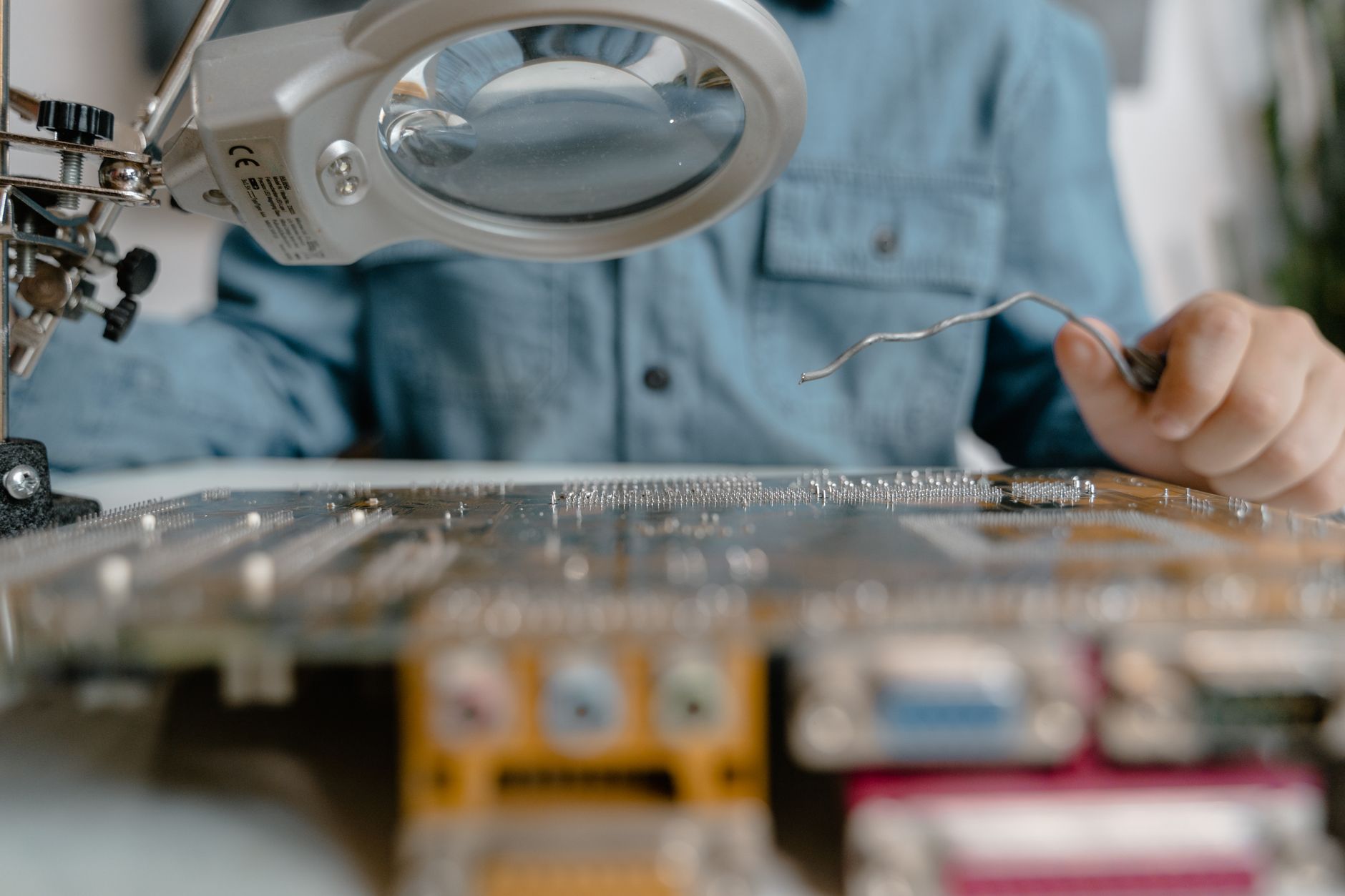
Infrared module sample testing should never stop at asking whether the image “looks clear.” The real purpose of infrared module sample testing is to separate detector performance, optical matching, interface readiness, environmental stability, and production consistency. A sample that outputs an image is not automatically ready for a project. A module that starts in a cold chamber may still suffer uncontrolled thermal drift. A clean laboratory image does not prove reliable performance in vehicle systems, UAV payloads, power inspection, perimeter security, or mobile robot platforms.
For engineering and procurement teams, the sample stage is where risks should be exposed early. If the evaluation only relies on a demo video or a supplier’s live preview software, critical integration problems may remain hidden until mechanical design, algorithm tuning, field testing, or pilot production. A disciplined sample test should create measurable evidence: what was tested, under which conditions, with which firmware, lens, power supply, interface, and host software.
What Should Infrared Module Sample Testing Check First?
The first step is to confirm whether the detector, optics, and electronics match the project requirement. Common uncooled LWIR modules use 640×512 resolution with a 12 μm pixel pitch and typically operate in the 8–14 μm band. Cooled MWIR modules are often available in 640×512 or 1280×1024 formats, commonly with 15 μm pixels and a 3–5 μm spectral band.
For general observation, temperature measurement, perimeter monitoring, and industrial inspection, an uncooled LWIR module such as SPECTRA L06 640×512 LWIR 12μm should be evaluated for NETD, defective pixels, startup behavior, non-uniformity correction, and long-term image stability. For long-range detection, high-speed targets, low-contrast scenes, and demanding optical payloads, a cooled MWIR solution such as SPECTRA M06 640×512 Cooled MWIR 15μm requires additional checks for cool-down time, cooler lifetime, peak power, heat dissipation, and startup current.
At minimum, the sample test record should include resolution, pixel pitch, frame rate, output bit depth, lens focal length, F-number, field of view, NETD, startup time, supply voltage, typical power, peak power, mechanical dimensions, weight, connector type, and firmware version. Procurement teams should not accept a table that only lists “typical values.” A usable sample review needs measured values, test conditions, measurement equipment, and the exact configuration used during the test.
It is also important to avoid testing the module as an isolated camera if the real product will use it as part of a larger system. A vehicle installation, UAV gimbal, fixed security turret, or handheld inspection device may introduce different thermal, vibration, power, and latency conditions. The sample plan should reflect the final application as early as possible.
How Do You Measure NETD, Defective Pixels, and Image Uniformity?
NETD should not be judged only by a specification line such as “≤40 mK” or “≤50 mK.” The test report should state blackbody temperature, ambient temperature, integration time, lens F-number, frame rate, and whether image denoising or digital filtering was enabled. Without these conditions, NETD data is difficult to compare across suppliers.
A practical engineering method is to use a stable blackbody at 30°C, keep the ambient environment near 25°C, allow the module to stabilize for 10–15 minutes, and then capture multiple frames. Compare noise behavior after 1 minute, 10 minutes, and 30 minutes from power-on. If the image shows obvious gray-level drift before and after thermal equilibrium, the downstream algorithm may need extra compensation. That shifts risk from component selection to system integration.
Defective pixels should be classified, not just counted. A test should distinguish dead pixels, blinking pixels, clustered defects, edge defects, row noise, and column noise. Single-point defects can often be corrected through NUC and interpolation. Continuous bad pixels, visible row noise, or column noise are more serious because they can interfere with detection, tracking, segmentation, and hotspot recognition algorithms.
A robust test should capture at least 100 frames each under a uniform blackbody scene, a low-temperature scene, and a high-temperature scene. The report should record the number of bad pixels, their positions, defect clustering, row or column noise amplitude, and the difference before and after NUC. For power equipment hotspot detection, the important question is not only whether the image looks sharp, but whether the module can distinguish small temperature differences reliably under realistic backgrounds.
For terminology and measurement concepts, teams can refer to ISO 18251-1:2017, which describes characteristics of infrared thermography systems. For image sensor characterization methods used in broader machine vision contexts, EMVA 1288 is also useful as a reference framework, although infrared modules may require additional application-specific tests.
How Do You Verify Interfaces, Latency, and Software Integration?
A sample test must prove that the interface can be integrated, not merely displayed in the supplier’s demo software. Common infrared module outputs include MIPI, Camera Link, GigE, USB, BT.656, BT.1120, LVDS, HDMI, and proprietary digital interfaces. The test should cover frame-rate stability, dropped frames, timestamp behavior, trigger or synchronization signals, SDK access, register documentation, firmware upgrade method, and production programming workflow.
For multi-sensor systems, synchronization is critical. Engineering teams should timestamp thermal video, visible video, IMU data, radar data, or other sensor streams on a shared time base. The end-to-end latency should then be measured against the system requirement. For AI recognition, target tracking, driver assistance, or gimbal stabilization, a visually acceptable image can still be unusable if latency is unstable or timestamps are missing.
Dual-band modules require more detailed checks. For example, a solution such as FUSION LV0625A 640×512+2560×1440 MIPI 35mm should be tested for thermal-visible boresight error, calibration file accuracy, registration drift after reboot, MIPI bandwidth margin, exposure coordination, and frame synchronization. If the supplier can only provide a viewer application but cannot provide an SDK, protocol description, sample code, register map, or production flashing procedure, the integration risk is still open.
Networked systems should also consider interoperability requirements. If the product architecture depends on video streaming, device discovery, or IP-based management, the team should check whether the module or system can align with relevant profiles and service expectations from organizations such as ONVIF. Even when a project does not require formal ONVIF conformance, early review of stream format, metadata, control commands, and authentication can prevent late-stage redesign.
When Should Environmental Testing Include Temperature, Vibration, and Power?
Environmental testing should not be skipped during sample evaluation. At minimum, an infrared module sample should be tested at -20°C, 25°C, and 60°C for both startup and continuous operation. Vehicle, airborne, outdoor, and unattended security projects should usually extend the range to -40°C to 70°C, depending on the final requirement.
At each temperature point, the module should run for no less than 2 hours. Record startup time, image drift, NUC frequency, housing temperature rise, power consumption, and any image artifacts. Uncooled modules often show increased noise at high temperature. Cooled modules require extra attention to cooler startup current, cool-down time, hot-side heat rejection, and whether the mechanical design provides enough thermal margin.
Vibration testing should reflect the actual installation condition. UAV payloads, vehicle systems, and pan-tilt platforms should be powered during vibration tests when practical. The test should check connector looseness, intermittent output, image tearing, focal plane shift, focus change, image jitter, and mechanical resonance. A sample that passes a static bench test may fail once installed on a moving platform.
Power testing is equally important. The supply should cover nominal voltage plus and minus 10%, or the actual project tolerance if stricter. Engineers should record inrush current, peak current, ripple sensitivity, brownout behavior, and recovery after abnormal power interruption. Some modules can output a clean image under a laboratory power supply but fail when connected to a shared vehicle power bus, UAV battery, or long cable harness.
For cooled modules, the power profile should be recorded from startup through steady-state operation. Peak startup power may determine cable gauge, power regulator capacity, connector selection, and thermal design. For uncooled modules, lower typical power does not eliminate the need to test supply noise sensitivity and startup repeatability.
Infrared Module Sample Testing vs Demo Image Review
A demo image review asks, “Does this look good?” Infrared module sample testing asks, “Can this module meet system requirements repeatedly under documented conditions?” These are different levels of evidence.
A demo may use a carefully selected lens, ideal ambient conditions, supplier-tuned image processing, and a scene that flatters the sensor. A project sample test should use the actual or equivalent lens, real interface, target host platform, representative power supply, and realistic thermal scenes. The team should also confirm whether the sample firmware is the same branch intended for production.
This distinction matters during procurement. A lower unit price may become expensive if the module requires custom driver work, repeated NUC tuning, extra thermal compensation, or mechanical redesign. Conversely, a module with a higher sample cost may reduce total project risk if documentation, SDK maturity, interface stability, and production quality control are stronger.
For AI-enabled systems, sample testing should include algorithm input requirements. If the project uses a board-level AI multi-band system such as NEXUS LV0619B AI multi-band Ethernet/SDI, acceptance should cover thermal image quality, visible image quality, synchronization, preprocessing, inference latency, metadata output, and performance on field data. AI performance cannot be inferred from a single clean thermal preview.
How Should You Write an Infrared Module Sample Test Report?
The final report should classify the sample as “approved,” “approved with conditions,” or “not approved.” Avoid vague conclusions such as “good image quality.” A useful procurement and engineering report should include clear acceptance lines.
Recommended acceptance items include measured NETD, defective pixel count, 30-minute thermal drift, interface dropped-frame rate, end-to-end latency, wide-temperature startup, continuous operation stability, and documentation completeness. If any item differs from the specification, the report should state the test condition, measured result, supplier explanation, and proposed corrective action.
A first-round evaluation should use no fewer than two samples so the team can compare unit-to-unit consistency within the same batch. For critical projects, conduct at least 72 hours of continuous operation before design-in. Before final selection, require the supplier to provide the full datasheet, ICD or interface control document, SDK, firmware revision history, lens parameters, mechanical drawings, test report format, and production acceptance standard.
Procurement should not select an infrared module only by the lowest unit price. Engineering teams should not approve a module only because a short demonstration video looks impressive. The purpose of sample testing is to close measurable risks before the cost of change becomes high.
FAQ
Q1: Do you need a blackbody for infrared module sample testing?
Yes. Without a blackbody, the team can only make subjective image judgments. A blackbody is needed to evaluate NETD, uniformity, thermal drift, and temperature measurement stability with repeatable conditions.
Q2: If the sample image looks clear, can we move directly to a pilot run?
Not recommended. Before a pilot run, the team should verify interface stability, wide-temperature startup, continuous operation, power disturbance recovery, latency, and documentation completeness.
Q3: Are the test priorities the same for uncooled LWIR and cooled MWIR modules?
No. LWIR testing focuses on NETD, NUC, defective pixels, thermal drift, startup behavior, and power. MWIR testing also needs cool-down time, cooler lifetime, hot-side thermal design, startup current, and long-range optical performance.
Q4: What should be tested for an AI infrared imaging project?
In addition to module-level image quality, test synchronization, latency, output bit depth, preprocessing format, metadata, and algorithm performance on field data. The AI pipeline should be accepted as a system, not as separate thermal and visible image previews.
Q5: How many infrared module samples should procurement request?
For a first evaluation, request at least two units from the same batch. For high-risk projects, add longer continuous operation, wider temperature coverage, and sample-to-sample comparison before approving the module for design-in.